26 April
|
The brake master cylinders have now been ‘bench bled’ (though without
removing them), and the feel is much better. I’ve dispensed with the three
individual fluid reservoirs. They were prone to leakage and made access to
the master cylinders difficult. I now have a single reservoir bolted to the
back of the wheelarch.

The carburettor’s been stripped and cleaned, air passages and jets
blown through, though with no obvious fault spotted. I measured jet sizes and
replaced one of the primary jets with one from my tuning kit which better
matched the size of the other. I’ve also measured all plug lead resistances
and re-checked coil resistances, etc. and found no fault. I’ll have another
go at running the motor next week and see if I can narrow anything down.
|
01 May
|
Made some passenger seat supports from aluminium channel, and also
cut some for the MX5 seats. I’ve been trying to find a way of not drilling
additional holes in the floor for the MX5 seats, but think this is going to
defeat me.
Gerry’s header tank and support bracket delivered. The bracket mounts
it a couple of inches too low – it needs to be the highest point in the
system. A couple of plates can be made out of aluminium to raise it up to the
level where the previous tank was mounted. Other than that, the Rover top
hose can be cut in two to fit both into and out of the header tank. The fan
thermoswitch, I now realise, screws into the boss at the top of the radiator.
All in all, the cooling system is simplified with fewer joints.
 
I’ve fitted a valve in the fuel tank vent, one that operates both
ways at a small pressure. This should help to stop the fuel smell, but was a
bit expensive.

At last a communication from Speedy Cables to say the speedometer
should be ready by the end of next week. They really haven’t lived up to
their name, this was sent to them on 21st February!
|
04 May
|
The engine’s been running again (after replacing a blown diode
bridge). No sign of the previous misfire, but still a lot of top-end clatter
to be investigated. Cooling system almost completely continent! The dwell’s
checked OK at around 35 degrees.
Checked the wipers with the engine running – unfortunately the fast
speed isn’t sufficiently faster than the slow speed to comply with IVA
requirements, so I’ve ordered a new motor. I’ve also ordered some switch
identification stickers.
Spent some time making seat brackets to adapt the MX-5 seats. The
seats sit very low and are compliant with IVA requirements for seat belt
height with a good margin – nearly 2 inches!
More time spent bleeding the brakes. Hopefully getting a bit less
spongy.
|
13 May
|
Fitted the new wiper motor, notable increase in speeds, though not
yet checked frequency. Speedometer received back, calibrated, and fitted.
Spent a bit of time tidying under the bonnet, and some time on seat frames
and locations to aid transfer of the MX-5 seats.
The fuel pressure gauge doesn’t work properly despite now being
correctly wired. It really needs some advanced diagnostics, though currently
I’m suspecting the sender unit. It seems to give an output voltage of around
200mV when the fuel pump’s on, which sounds much too low.
I’ve been filling in forms and collating paperwork in preparation for
sending off with the IVA application. Probably do this when I’m back from
holiday in a couple of weeks. There’s really not too much left to do on the
car.
|
10 June
|
Big step forward is I submitted the IVA test application a week ago.
This coming Saturday I’m trailering the car to my MoT garage for a sort of
pre-MoT and to help me balance the brakes. Worked out I needed to trailer the
car around six times (maybe more) so in the absence of a very local hirer
I’ve bought secondhand a neat Brian James four-wheel trailer which fits in the garage.

I’ve spent a bit of time ‘snagging’ and getting things in order for
the test, ensuring all wiring’s covered in convoluted conduit, bolts are
sticking through nuts properly, and pipes and wiring are well supported. I’ve
also obtained a new timing light and gastester to replace my 30-year-old ones
which didn’t work any more! I’ve
adjusted the timing to 10 degrees BTDC static, vacuum advance disconnected. I
think this is a reasonable starting point. I’ve adjusted the carburettor to
give CO levels of around 3% which is well within the allowable for the age of
engine.
I’ve started to cut out footwell carpets from a roll I got cheap at a
local autojumble. Although patterns are now made for my own, I’m not
confident of them being finished before IVA test time.
Still some niggles – the engine rattle being the largest, sounds
tappety but I’ll get a view from Andy at Grappenhall Motors on Saturday. Not
yet fixed the fuel pressure gauge, though I’m suspecting a faulty sender
unit, and the float on my fuel gauge sender has sunk! I’ve sent for a brass
replacement from Moss.
|
05 July
|
The ’pre MoT’ was a proper MoT – which I failed on brakes, rear brake
and handbrake efficiency too low. The trip also revealed some persistent
clutch drag which caused dome difficulty engaging first and reverse. A second
visit with tightened handbrake didn’t turn out much better. I puzzled over it
for a while – then realised I’d been misled into believing I needed a strong
bias towards the front brakes. The set up I’ve got is MGB – the original MGB
had single-line hydraulics, with no pressure limiting valve, so the balance
bar setup should be 50:50 front to rear. However, my Hawk has a little more
rearward weight bias, and has high friction (Greenstuff) front pads –so I
need a little bias to the rear – not too much, which would upset the IVA.
I’ve gone back to first principles to calculate the setup – I may
send this to Phil to see if he thinks it’s worth publishing.
I swapped the 0.7” master cylinder on the rear brake line with the
0.625” clutch master cylinder, and adjusted the balance bar to give
approximately 53% bias to the rear brakes. This solved both problems – the
clutch operating lever has more stroke and now allows quiet and easy
engagement of all gears, and the brakes passed the MoT today!
Rear drums have been drilled with inspection holes in case the IVA
people are applying the letter of the regulations.
 
The MoT emissions test showed that somehow my CO emissions were less
than 1%. So much for the Gastester. I increased them to a healthier 3%!
I’ve spent some time with carpets to make the interior look a bit
presentable while I wait for Gerry’s carpet set to be produced, though
there’s a bit more to do. I’ve sorted the fuel gauge with a new float. I’ve
tidied up a number of loose ends in advance of the IVA test – which is booked
for 8:00 on 23 July.
 |
Sunday, 6 July 2014
Towards the MoT

Friday, 18 April 2014
Almost working .....
|
14 Mar
|
Just about finished covering the steering wheel - looks almost modern. Also been working to
wire ammeter (needs testing), and new foglight switch to comply with latest
IVA. Sourced some new washer jets with adjustable nozzles – the previous ones
with fixed nozzles aimed too low. Spent some time on hydraulics, bleeding
brakes and clutch.
Found the front overrider support brackets don’t line up with where I
think the overriders should be and will have to have some drop plates fitted
to lower the level by a couple of inches. There are a lot of fiddly
activities at the moment, lots of time spent achieving not much!
I need to check the tappet clearances – the rough running of the left
bank was I suspect due to low compression on one or more cylinders due to the
valves not closing. One of the heads had more valve seat work than the other,
which may have to be compensated by shims under the rocker pillars.
|
|
17 Mar
|
Steering wheel’s finished and in place, but the padded boss looks a
bit naff and rather spoils the effect. I wonder if I can do something a bit
better?
The foglight switch and control is fitted and working.
I’ve also removed the carburettor and inlet manifold to check the
follower preload. I can see that it’s too high on No.3 cylinder, which I
already suspected of poor compression. I’ll do the checks slowly and
carefully over the next few days.
|
|
31 Mar
|
Obtained an MGB steering wheel padded boss, which as luck would have
it fits the steering wheel perfectly!
 
Four panels have been made in aluminium to fit under the dash, and
covered with leathercloth. These can’t be finally fitted until last – when
all the wiring’s fully sorted, the instruments are properly fixed and the
speedometer’s back from calibration (‘Speedy’ cables are taking forever – 5
weeks so far and a further delay of 3-4 weeks).
Tried shimming the rocker shafts to correct follower preload, but not
able to get all followers within tolerance. Shelled out for adjustable
pushrods, which are now fitted and adjusted.
Unfortunately having adjusted the preload, I tried the engine again (Mon
31st March), and the symptoms are unchanged. Time for some serious
diagnostics ….
Also tried while the engine was running, the clutch – I wasn’t very
convinced by the feel and sure enough it doesn’t disengage properly. I think
I’ll have to take the hydraulics apart, but first of all I might try to
disengage it mechanically to check the amount of axial movement required.
The delay with the speedo and the issues with the misfire and clutch
are delaying the time when I feel comfortable to book the IVA test.
|
|
05 April
|
Improved the rigidity of the fog lamp and reversing lamp by making a
small bracket to hook under the lip of the rear valance, fixed to the back of
the lamp and to the main attachment point. They feel nice and rigid now, not
forever being spun round every time I brushed against them!

I’ve also made a VIN plate. It looks just about passable, and the
text is large enough.
Some detailing – I’ve fitted a Tecalemit 2800 model grease gun in the
appropriate place under the bonnet. I think it will be decorative – can’t
beat my Wanner for any serious greasing!
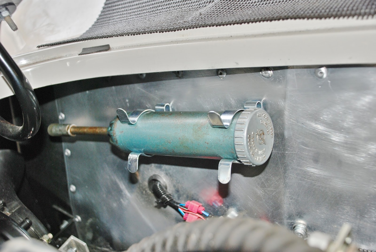
I’m now waiting for a fine day when I can get the car in the drive
and start to tackle the mechanical issues. I think the clutch will come
first.
|
|
13 April
|
Main job over the last week has been to tackle the clutch. This
involved removal of exhausts and propshaft, then separation of the
bellhousing from the engine and
partial withdrawal of the gearbox. I had the front end jacked high enough to
give access without complete removal of the gearbox. It was clear to see what
the problem was, the release arm was fouling the side of the bellhousing, but
what caused the misalignment wasn’t clear at first, but was probably some
incorrect assembly where the release fork met the thrust bearing. The pivot
pin was the correct one, 43mm outstand. Funny thing was, after very carefully
reassembling everything – and this isn’t easy – and reconnecting the
bellhousing, I got exactly the same symptoms, with only half a stroke of
pedal travel. I removed the slave cylinder and pushed the pushrod in and out
a few times, something seemed to fall into place and the pushrod didn’t go
back quite as far. I reconnected the slave cylinder and hey presto, full
clutch travel! As I had the propshaft off it was easy to check that the
clutch was disengaging properly.
A tip for anyone fitting the release fork: assemble the fork and
slipper pads to the release bearing before offering up the fork to the
bellhousing. The assembly can be held together with cable ties, elastic bands
or lockwire to be removed after installation. The pivot pin can be screwed
into place after locating on the release fork, and tightened with a shortened
or adapted spanner. Don’t forget to fit the pushrod before offering up the
release fork to the bellhousing.
While the exhausts were off I took the opportunity to make some final
adjustments and seal the joints with assembly paste, all except the
manifold-to-downpipe joint, which I’ve left untightened at present ‘just in
case’. I’m also improving the action of the handbrake, to get rid of some
internal binding of the compression spring, and contemplating making some
aluminium seat subframes that will adapt the MX5 seats to the existing floor
drillings.
|
|
17 April
|
Glorious Good Friday, spent working in the sunshine!
Front over-riders: made up some aluminium drop plates to lower the
over-rider supports, drilled the locations alongside the grill and trial
fitted the overriders. They look just about right, but of course will have to
come off again for the IVA test.

The handbrake actions been improved with some internal mods moving
the compression spring. The action is now more reliable.
Bled the brakes again by pressurising each system, but although no
bubbles at the wheels, I still must have air in the master cylinders as the
feel and action is poor. These will have to be disconnected and bled
individually like I did with the clutch.
For the first time the car’s moved under its own steam. Only to turn
in the road and re-enter the drive though! The clutch seems to work OK but gear
engagement was difficult. For now I’m putting this down to lack of oil circulation
through the gearbox, rather than any mechanical defect, and hope that it gets
better! I’d wired a test strobe in series with the plug for the suspect No.3 cylinder
when I fired up the engine, which flashed away giving me no cause to suspect the
spark. I removed the plugs and carried out a compression test, first on No.3,
expecting to find a low reading. I got 140psi which I was reasonably happy with,
though! Other cylinders varied between 150 and 165psi. Finally I repeated the
test on No.3 and it gave 155psi. I think overall the range is reasonable and low
compression isn’t a cause. I’ll probably check the carburettor next – I remember
my old Scimitar regularly blocking a jet and running rough.
Another concern is there’s a knocking coming from the engine, not sure
where, but now the exhaust joints have been quietened it seems louder. Further
investigation due.
|
Friday, 28 February 2014
Valentine's Day startup!
19 Jan14
|
Battery connected and testing started. Lights look OK with the
exception of the headlamp dipswitch, windscreen wipers don’t work and the
heater fan blows a fuse! Altogether at least as good as I expected!
Troubleshooting begins ….
|
||||||||||||||||||||||||||||||||||||||||||||||||||||||||||||||||||||||||||||||||||||||||||
09 Feb
|
Managed to sort out most of the electrics. The fan wiring was messed
up, I’ve now got it running but only on a single fast speed. The wipers
didn’t work properly with the rotary switch I was using (advantage being it’s
marked ‘wipers’) but after changing the brushes, fitting a new park switch
and 130 degree wheel to the motor unit, it’s now working with the
two-speed-and-park switch supplied with the loom. I need to check the speeds
are OK for IVA.
I’ve adjusted the float in the tank sender, after it was obvious it
was bottoming and giving a reading of quarter full when empty.
I’ve spent some time on the exhaust – not a great pleasure given the
recent poor weather and cramped garage access, but now much happier with the
fit-up, though getting a ground clearance of much over four inches is
challenging.
I’ve been focussing both on getting the engine ready for starting,
and on the IVA requirements. The engine’s now about ready – I’m not happy
with the arrangement of the cooling system really, having seen how many
joints I’ve ended up with. It’s now almost leaktight (at least
unpressurised). The sump’s filled with Halfords Classic 20/50 – which looks
remarkably like Duckham’s – and I’ve primed the pump with an electric drill
until 40psi on the gauge.
I’m just waiting to sort out the ballast resistor ignition circuit. I
looked at a number of diagrams on the net, but only one (MGB-V8 site)
correctly showed the need for a diode bridge. Without this, the starter runs
as soon as the ignition key’s turned to the first position. It’s actually
obvious from the various circuit diagrams I looked at, that as soon as the
ignition’s on, the current runs to the starter solenoid, but I made the
mistake of wiring it that way first. The kit needed is a 35A Diode Bridge
KBPC 3504, which costs buttons from Maplins. I’m just waiting for this and
then – fingers crossed – should be able to fire up.
I called at the petrol station to fill my two-gallon Valor can with
petrol (I do this every year for the lawnmower – always half expecting to be
refused, as although the can has held petrol continuously for over 75 years
it’s considered ‘non-PC’ these days!) which has been transferred to the tank.
I’ve run the pump to prime the filters and carburettor, fixing the inevitable
couple of leaks. Also turned the engine over a few times – without plugs – on
the starter motor.
|
||||||||||||||||||||||||||||||||||||||||||||||||||||||||||||||||||||||||||||||||||||||||||
16 Feb
|
Diode bridge arrived and I fitted it onto an aluminium backplate with
the ballast resistor, wiring it to a piggyback connector to the ‘start’
terminal of the ignition switch.

Valentine’s day – 14th – was historic, I reset the
ignition timing approximately, and the engine fired up quite readily, though
with blowing exhausts, water drips from hoses and a biblical oil leak from
the oil pressure gauge connection. Also a bit of an intermittent misfire from
the left bank. All in all, no worse than expected!
Next job is to get the clutch working. I’ve got a 5/8” master
cylinder with the Rover 7/8” slave cylinder, which means the stroke at the
slave is approximately half the stroke at the master, which seems to be about
1¼”. So far not much success bleeding the system – but I think I know why.
I’ve been using a vacuum pump which of course is drawing the slave piston
AWAY from the operating rod – I need to use a pressure system which forces
the slave piston onto the operating rod. As the rod stroke is only going to
be 5/8” this is quite critical!
Watch this space.
|
||||||||||||||||||||||||||||||||||||||||||||||||||||||||||||||||||||||||||||||||||||||||||
23 Feb
|
After some more concerted bleeding – the clutch may be working –
although the engagement seems a long way down the pedal travel. Hard to tell
until the engine’s running again and I can try and get it in gear. Think I’d
like the brakes functional too, first ….
Made a collapsible hub, with the intention of satisfying the IVA
requirements, but as it actually looks quite good I think I’ll retain it.
 
The
solid boss obtained from Scarborough Racing Developments is machined right
back to leave only the spline adapter and flange; this is drilled with four
6.5mm holes to suit the PCD of the rear face of the collapsible hub unit I
got from Europa Spares. At the business end I machined an adapter flange from
aluminium plate which mates with the collapsible hub and the steering wheel.

I’ve trial fitted one of the seats from the MX-5, which seems to give
an acceptable vertical height from the seatbelt anchor point. It may be best
fitted via an adapter frame to make best use of hole drillings. I’ll set some
time aside for this just before the IVA test, now I know it’s a goer.
|
||||||||||||||||||||||||||||||||||||||||||||||||||||||||||||||||||||||||||||||||||||||||||
24 Feb
|
Got to grips with the front suspension. I’m replacing the ‘pattern’
wishbone arms with refurbished OE items; the pattern parts haven’t got the
inner pivot bush welded on squarely, which doesn’t look good and while it may
or may not affect the suspension performance with rubber bushes it would
preclude any later fitting of poly bushes.
The front ride height’s always seemed an inch or so too high; I
thought this might be due to wind up in the rubber bushes, but also could be
due to incorrect springs. I carefully measured the spring when removed, and
calculated the length under load. Due mainly to being too long (10.3” free
length, rather than 9.9” for the pre-’72 roadster OE item), the length under
load comes out at between 0.4 and 0.5” longer than the OE spring (AHH6451).
Factored up taking into account the intermediate position of the spring along
the wishbone, this accounts for 1” of additional ride height. I now have a
pair of AHH6451 springs on order and hope this sorts the problem.
|
||||||||||||||||||||||||||||||||||||||||||||||||||||||||||||||||||||||||||||||||||||||||||
26 Feb
|
OE springs delivered amazingly quickly from Sussex Classics, offside
spring fitted. Springs are approximately 0.5” shorter than those from MGBHive
and have a smaller wire diameter (0.5” not 0.515”). This should cure the ride
height issue.

For anyone interested in the spring / ride height calculation - here it is:
Reflectors relocated to where the upper over-rider support’s going to
be. They now face squarely rearward.
|
||||||||||||||||||||||||||||||||||||||||||||||||||||||||||||||||||||||||||||||||||||||||||
28 Feb
|
Finished the front suspension, pleased to say that fitting the OE springs
has completely cured the ride height issue, lowering the front by about 1.75”
and leaving the indicators just above the minimum required height for the IVA
test (350mm).
Also fitted N/S pads and bled the brakes, front and rear. I think they
need bleeding some more to improve the pedal feel, but was able to test the pressure
switch and brake lights.
|
Sunday, 19 January 2014
November 13 to January 14 progress
|
15 Nov
|
Axle out, halfshafts stripped and new bearings fitted. I used one of
the old drive flanges held in place with the axle nut to help knock out the
shafts. The press came in handy again for bearing removal and fitting, the forces
involved are 1-2 tonnes. The axle’s ready to go down to Shropshire for the
new CWP to be set up. The 3.07 crownwheel is appreciably thinner than the 3.9
one – a comforting observation!
Made and fitted inner sills in 2mm alloy. Not (yet) backfilled with
foam.
|
|
30 Nov
|
Completed the wiring inside the boot, wired up the fuel pump, tidied
up the vent and fuel lines and protected all rear loom wiring with split
convoluted conduit.
In the process of tidying all the underbonnet wiring and securing
with conduit. Running the front light wires out through grommeted holes in
the inner wings.
Acquired wipers and side repeaters at the Classic Car Show, also
changed the fuel pressure sender for one with 1/8NPT thread. This is now
installed on top of the Filter King.
Axle delivered to Andy Stewart in Shifnal. Apparently some Moss CWPs
are noisy – fingers crossed this one’s not too bad. Looking forward to
getting this finished and refitting the axle. The car’s really difficult to
work on, immobilised in the garage.
The shortshift has been returned from welding – an excellent job too.
I’m now in the process of fitting it.
|
|
20 Dec
|
Gearchange completed, including a mod to the existing linkage which
removes the need to acquire any other components.
  
A small metal plated is glued and screwed to this to engage the reversing light switch.

Axle collected and re-fitted, Andy looks to have done a thorough job,
stripping, repainting and fitting a new cover plate. I’ve filled with EP80-90 diff oil.
Handbrake lever welded and handbrake re-fitted and connected.
|
|
10 Jan 14
|
Managed to find some time over the Christmas break to do a few jobs.
I’ve welded the handbrake actuation lever to the bottom of the handbrake
lever and connected the rear brakes. I’ve also welded a couple of components
in the throttle linkage, which I’ve modified slightly to remove some unwanted
deflection, and made and fitted an accelerator pedal.
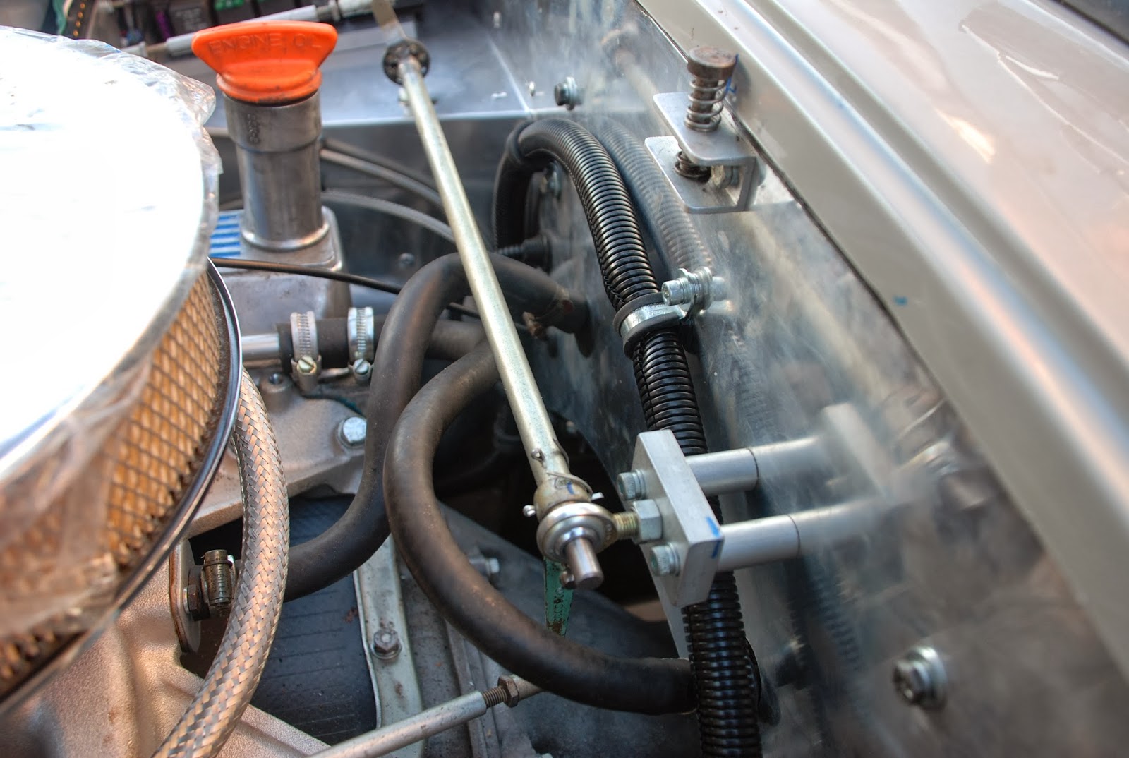
The side repeaters are now fitted and wired, and the wiring for the
headlamps and front indicators has been completed. The wiper motor and washer
are now wired up.
I think I’ve found a way of fitting the rear fog and reversing lamps
which overcomes the height issue for IVA. The lights are fitted to short
sections of 5/8” aluminium round bar which are retained through the lower
holes prepared for the over-riders. A bolt fitting into the inside end of the
aluminium bar will also retain the exhaust pipe hanger.
When I’ve got these lights fitted and wired up I can start testing
the electrics – finally starting the commissioning phase!
|
|
18 Jan 14
|
Reading the 2013 revisions to the IVA, realised my rear fog lamp
won’t pass, so have obtained an electronic gizmo from Cartek which needs
fitting. I’ve tweaked the bends in the exhaust pipes so the rear hangers line
up with the over-rider supports. I’ve made up and welded some half-decent
rear straps and the exhaust is now in place. I need to make some adjustments
and shortening of the rear sections, and find a way of sticking the tailpipe
trims on.
The fog and reversing lamps are now fitted using an aluminium spool
piece through the bodywork in line with the lower over-rider support bracket,
the inside face of which supports the exhaust. It hasn’t improved the
aesthetics, but the lower edge of the lights is now more than 30cm from the
ground, which should tick the IVA box.

I think the electrics are wired to the point where I dare connect a
battery and start testing, so as soon as I’ve finalised the exhaust, that’s
the next step.
|
Thursday, 14 November 2013
fiddly bits - October-November
|
18 Oct
|
I’ve fitted horns, coil and ballast resistor, and wired up the
alternator, which now has a drive belt too! The rear trim covering the seat
belt support frame is in place. The nearside door trim is also in place, but
needs some fettling. It doesn’t fit well around the piece of moulded
fibreglass that covers the door hinge, and will have to be re-worked. I’ll
probably take the opportunity to replace the ‘fir tree’ fasteners, which only
seem to work once, with some spring clips.
A steering column extension has been made in aluminium and is ready
to be drilled so it can be located in place. This supports the indicator switch
– though I’m uncertain where I’m going with that. I wanted a switch that
dipped and tooted as well, but the one I’ve got looks clumsy and almost
obscures part of the speedo. The Ace dashboard layout preceded column-mounted
switches, and somehow they don’t look right.
I’ve obtained all exhaust components, bent the pipes as required
(they’re shallow bends and my Machine Mart bender does the job, with a little
care), and the offside system is complete and trial assembled in position.
I’ve managed to get 5” ground clearance (about the maximum feasible), though
this may reduce when I sort the front springs. I’m not yet happy with the exhaust
hangers, there’s more work to do there.
I’ve removed and covered the dashboard, which is ready to go back and
be fitted out. Note this exercise will be repeated post IVA.
|
|
02 Nov
|
The dashboard’s in place, and a number of switches and instruments
are now hard-wired in, though gauges are not yet clamped in position. The
steering column extension is fitted and clamped in position. I note the
steering wheel boss needs a little machining work to match the tapered
section of the steering column, just behind the splines.
I’ve been busy under the bonnet too. I’ve finally primed and fitted
the tappets and pushrods, torqued up the manifold and fitted the carburettor.
The static timing has been crudely set and ignition leads and plugs are in
place. I’ve made and fitted a battery tray from 2mm alloy sheet, piped the
fuel feed to the carburettor and fitted heater water pipes and hoses.
 |
|
07 Nov
|
Fitted the oil pressure gauge pipe, and battery connections – though
I have to finish off the isolator switch mounting on the scuttle under the
bonnet. Also decided to have a go at making the ‘short-shift’ conversion on
the Rover gearchange, having received an offer of alloy welding. I think
it’ll look a little less agricultural than the Sherpa change.
|
|
14 Nov
|

Finished the isolator switch, and I’ve been wiring dashboard switches, fitting seat runners to the driver’s seat,
machined a conical female taper into the steering wheel boss and generally fiddled
about. I’m going to the classic car show at the NEC this weekend with a shopping
list of odds and sods. I’ve had the ‘short-shift’ welded, though I’ve yet to see
the result, and I’ve also found someone who’ll install the new CWP into the axle.
The cost/difficulty of obtaining special tools is a factor. Next job’s to take
the axle out and strip the halfshafts, ready to be operated on!
|
Monday, 30 September 2013
September Update
27 Aug-18 Sep
|
Holidays and family visiting have prevented much progress, though I
now have all three looms joined together and most of the holes drilled in the
dashboard. Windscreen fitting is required before finally fitting the
dashboard. Other than that I’ve been making components for the new handbrake.
Hope to get stuck in better before the end of September!
|
21-29 Sept
|
The handbrake lever’s finished apart from the weld required when the
lever that connects with the cable is in the ideal position. The cable’s also
fitted temporarily. The capscrews didn’t help the manifold problem – they
were even more impossible than the hex heads! With some difficulty it is just
possible to get a spanner on the offending screws and tighten them, but it
needs patience.
I’ve replaced the Lucas starter motor with a geared one from Powerlite. The Lucas unit needed
repair to the main terminal which wouldn’t have been easy, and when all’s
said and done its condition was unknown. I wanted to have the best chance of
startup when the time came. The Powerlite unit is much smaller and lighter.

Faced with an ultimatum to clear the spare bedroom (!) pending guests
staying, the windscreen is now fitted! A bit of a struggle drilling the holes
for the retaining screws, and a bit stiff the day after! Fitting needs
careful measurement to ensure compliance with the dimensions recommended by
Gerry’s Build Manual.
   
Following this the dashboard’s been drilled for the instruments and
switches, and is now in place, though will need to be removed for covering
with leathercloth. The intermediate steering columns been removed and had the
grooves milled in place to receive the clamp screws.

I’ve fitted the trim covering the seat belt mount, and the seats are
loosely in place. I’ve also fitted the nearside door trim – though this will
have to be removed later for remedial work. I made a template from thick
paper and accurately drilled the holes for the ‘firtree’ fasteners – but
really these are one-shot fasteners, and are damaged by removal.
Unfortunately the fit around the GRP moulding that covers the door hinge
isn’t good and I need to re-work the trim panel to increase the clearance
here and make it fit better – which means fitting new firtree fasteners which
in turn means separating the cloth from the hardboard backing.

Gerry’s propshaft has arrived and is now fitted. Good to see it’s
fully greasable!
The next major job will be the exhaust. At the moment I’m proposing
to build the system myself, using primary and secondary absorption silencers,
and 1.75” pipe. This is really a bit too large but silencers taking smaller
diameters are not readily available, it seems. I propose to make up a couple
of dummy silencers with wood and card to find the best positions.
I have the remaining ignition components – leads, coil and ballast
resistor – on order, also over-riders. As of tomorrow – 1st
October – I become semi-retired, so hopefully progress might be a bit faster!
|
Sunday, 15 September 2013
August progress
06-17 Aug
|
Steam Rally at Chelford yielded material to make the cross-linkage
behind the engine block (from a commercial vehicle wiper linkage!), which
coupled with three Rose joints and some linkage components I’ve had in stock
for many years, has seen the throttle linkage almost complete – except for a
single ball joint to fit to the carburettor .
I’ve also loosely fitted the engine bay loom in place. The relay
stack and fuse box will need some ingenuity to fit around the throttle
linkage on the footbox top.
I’ve distracted myself with a number of small jobs, I really need to
concentrate on finishing one before moving on. I’ve been planning the alternator ‘bracket’
– which will be just a long sleeved bolt going through the pivot brackets.
The bolt preload compresses the sleeve and prevents the load of the
alternator stressing the threaded connection. The previously mentioned
commercial wiper linkage has yielded a turnbuckle which I may be able to use
as the tensioning link. A suitable long bolt has been obtained from the
Tatton Autojumble today. Other finds included a gearknob, 45 degree cooling
hose elbow (now fitted to the radiator bottom outlet) and a metal tube – ex
Norbar torque wrench handle – which will make an ideal handbrake lever.
|
18 Aug
|
Fitted the demister ducts under the demister chrome outlets. This
needed a bit of ingenuity, the ducts have each been drilled in two places to
take a piece of 6mm diameter brass bar, cross-drilled and tapped M5 to take
the screws which fit through the chrome outlets .Gaffer tape may be needed to
make sure it’s all ‘airtight’!
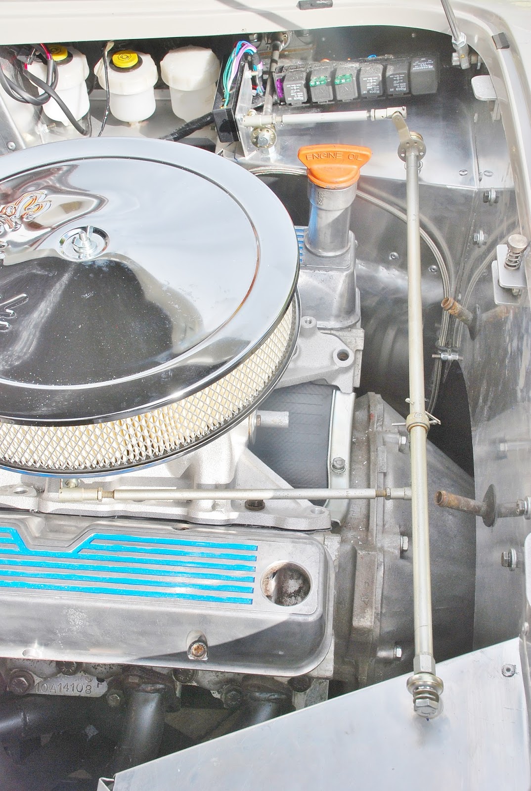
The top of the driver’s footbox is now sorted, the relay stack and
fuse box have been fitted around the throttle linkage and the result looks
quite acceptable. A picture’s worth a thousand words …… I’ve started to run the loom around the
engine compartment. There’s not too much slack to reach the earth on the
nearside chassis, so needs a bit of care and thought. There seems a lot of
wire for the N/S lights – I’ll check that again!
 |
22-24 Aug
|
Using some thick aluminium plate bought at a local steam fair, made a
plinth for the relay stack, and a bracket for the alternator. The
alternator’s now fitted, (some modification to original plan) not without a deal of fiddling, turning, milling and
drilling! I’ve incorporated a turnbuckle in the tensioning link, making
adjustment easier and more positive than the usual slotted bracket
arrangement. Next job is making a spacer for the water pump pulley, so that
all pulleys can sit in line.
|
25-26 Aug
|
Used a piece of ¼” aluminium plate to make a spacer for the water
pump pulley. Sounds easy – but took a good few hours. The spacer needed to be
like a large washer, about 3.5” outside diameter and 2.25” inside diameter.
There are three ¼” holes on 3” pitch circle diameter. The inner diameter is
stepped (2.25” and 2.35”) and the outer face needs a raised spigot to locate
the original pulley. A combination of milling, drilling and turning to
produce, now fitted and all pulleys aligned.
To make clearance for the V belt drive to the alternator, the header
tank had to be moved forward about an inch. While under the bonnet, replaced
the offside block drain tap (which slightly fouls the blockhugger manifold)
with a ¼” BSP taper plug. Noted that the two lower central screws holding
each manifold to the head are practically impossible to manipulate with a
spanner. These need to be replaced with 3/8” UNC x 1.1/4” long socket
capscrews.
|


Subscribe to:
Posts (Atom)