06-17 Aug
|
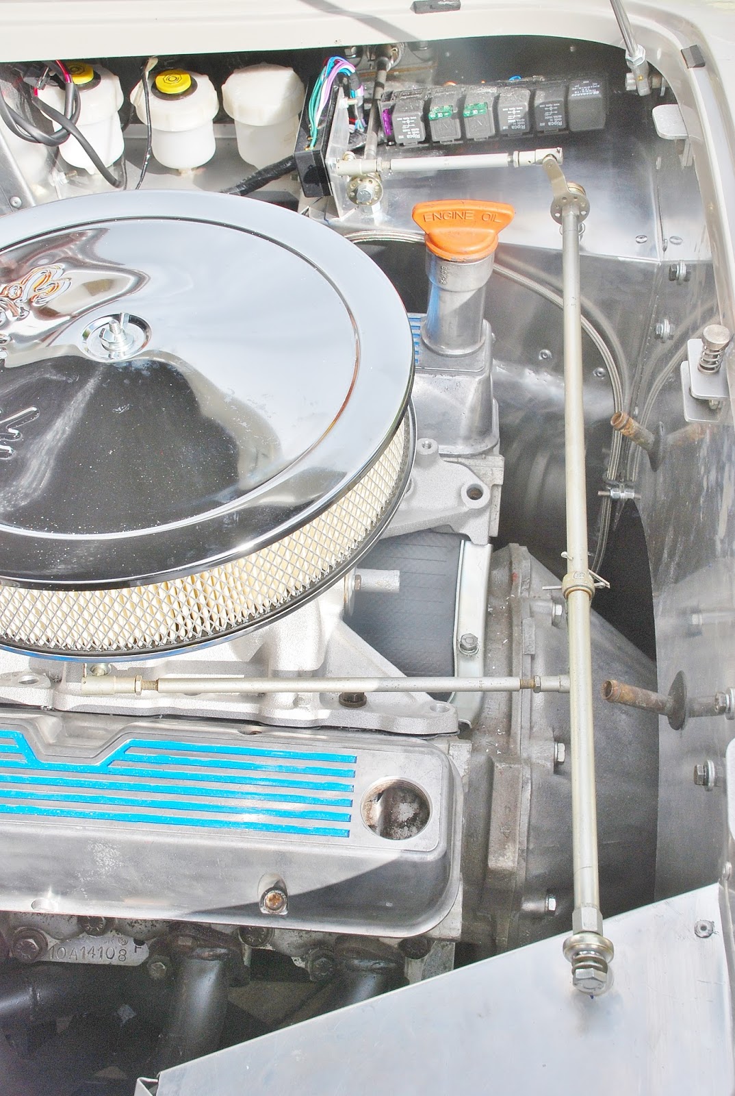
Steam Rally at Chelford yielded material to make the cross-linkage
behind the engine block (from a commercial vehicle wiper linkage!), which
coupled with three Rose joints and some linkage components I’ve had in stock
for many years, has seen the throttle linkage almost complete – except for a
single ball joint to fit to the carburettor .
I’ve also loosely fitted the engine bay loom in place. The relay
stack and fuse box will need some ingenuity to fit around the throttle
linkage on the footbox top.
I’ve distracted myself with a number of small jobs, I really need to
concentrate on finishing one before moving on. I’ve been planning the alternator ‘bracket’
– which will be just a long sleeved bolt going through the pivot brackets.
The bolt preload compresses the sleeve and prevents the load of the
alternator stressing the threaded connection. The previously mentioned
commercial wiper linkage has yielded a turnbuckle which I may be able to use
as the tensioning link. A suitable long bolt has been obtained from the
Tatton Autojumble today. Other finds included a gearknob, 45 degree cooling
hose elbow (now fitted to the radiator bottom outlet) and a metal tube – ex
Norbar torque wrench handle – which will make an ideal handbrake lever.
|
18 Aug
|
Fitted the demister ducts under the demister chrome outlets. This
needed a bit of ingenuity, the ducts have each been drilled in two places to
take a piece of 6mm diameter brass bar, cross-drilled and tapped M5 to take
the screws which fit through the chrome outlets .Gaffer tape may be needed to
make sure it’s all ‘airtight’!
The top of the driver’s footbox is now sorted, the relay stack and
fuse box have been fitted around the throttle linkage and the result looks
quite acceptable. A picture’s worth a thousand words …… I’ve started to run the loom around the
engine compartment. There’s not too much slack to reach the earth on the
nearside chassis, so needs a bit of care and thought. There seems a lot of
wire for the N/S lights – I’ll check that again!
 |
22-24 Aug
|
Using some thick aluminium plate bought at a local steam fair, made a
plinth for the relay stack, and a bracket for the alternator. The
alternator’s now fitted, (some modification to original plan) not without a deal of fiddling, turning, milling and
drilling! I’ve incorporated a turnbuckle in the tensioning link, making
adjustment easier and more positive than the usual slotted bracket
arrangement. Next job is making a spacer for the water pump pulley, so that
all pulleys can sit in line.
|
25-26 Aug
|
Used a piece of ¼” aluminium plate to make a spacer for the water
pump pulley. Sounds easy – but took a good few hours. The spacer needed to be
like a large washer, about 3.5” outside diameter and 2.25” inside diameter.
There are three ¼” holes on 3” pitch circle diameter. The inner diameter is
stepped (2.25” and 2.35”) and the outer face needs a raised spigot to locate
the original pulley. A combination of milling, drilling and turning to
produce, now fitted and all pulleys aligned.
To make clearance for the V belt drive to the alternator, the header
tank had to be moved forward about an inch. While under the bonnet, replaced
the offside block drain tap (which slightly fouls the blockhugger manifold)
with a ¼” BSP taper plug. Noted that the two lower central screws holding
each manifold to the head are practically impossible to manipulate with a
spanner. These need to be replaced with 3/8” UNC x 1.1/4” long socket
capscrews.
|
Sunday, 15 September 2013
August progress


Subscribe to:
Post Comments (Atom)
No comments:
Post a Comment